






Technical 1700-1850°C | 1800-1950°C | Table of Contents
The Fundamental Si₃N₄ Sintering Challenge
Silicon nitride presents a unique paradox in ceramic processing: it is one of the most valuable structural ceramics precisely because of properties that make it extraordinarily difficult to manufacture. Si₃N₄ is a covalently bonded compound with self-diffusion coefficients on the order of 10⁻¹⁴ cm²/s at 1800°C-roughly six orders of magnitude lower than oxide ceramics like Al₂O₃. Solid-state sintering via vacancy diffusion is therefore kinetically impossible within practical timeframes.
Compounding this challenge, Si₃N₄ is thermodynamically metastable at the temperatures required for densification. Above approximately 1800°C at atmospheric pressure, it decomposes exothermically into liquid silicon and nitrogen gas (Si₃N₄ → 3Si(l) + 2N₂(g)). This decomposition temperature lies directly within the window needed for effective liquid phase sintering.
The manufacturing solution requires simultaneous control of three variables: (1) Liquid phase formers (Y₂O₃-Al₂O₃, MgO, rare earth oxides) that create a transient silicate melt enabling solution-reprecipitation; (2) Elevated nitrogen overpressure that shifts the decomposition equilibrium to higher temperatures per the Clausius-Clapeyron relation; and (3) Precise thermal profiles that balance densification kinetics against α→β phase transformation and grain growth. Only through mastery of all three can >99.9% theoretical density be achieved.
Raw Powder Specification & Sintering Additive Design
Final component performance is predetermined at the powder stage. Every parameter-from α/β ratio to oxygen content to additive chemistry-is engineered to control densification kinetics and final microstructure.
α-Si₃N₄ Powder Specifications
Phase Purity: ≥95% α-Si₃N₄ (α transforms to β during sintering; pre-existing β seeds control grain morphology)
Particle Size (D50): 0.2-0.5 μm (submicron maximizes surface energy driving force for sintering)
BET Surface Area: 10-20 m²/g (optimal reactivity without excessive agglomeration)
Oxygen Content: 1.0-2.0 wt% (surface SiO₂ layer participates in liquid phase formation; too low inhibits wetting, too high degrades high-temp properties)
Metallic Impurities: Fe, Ca, Na each<50 ppm (prevent low-melting eutectics and grain boundary weakening)
Free Silicon:<0.5 wt% (excess Si indicates prior decomposition)
Sintering Additive Systems
Additives react with surface SiO₂ to form a Y-Si-Al-O-N (YASAN) oxynitride melt at ~1700°C. This liquid wets Si₃N₄ grains, enables solution-reprecipitation, and controls β-grain aspect ratio:
Y₂O₃ + Al₂O₃ (5-8 wt%): Industry standard; optimal melt viscosity, wetting angle<30°, balanced densification rate and grain growth
MgO / MgSiN₂ (2-4 wt%): Lowers eutectic temperature by ~100°C; faster densification but coarser grains
Rare Earth Oxides (Lu₂O₃, Yb₂O₃, Sc₂O₃): Higher cation field strength → more refractory grain boundaries → superior creep resistance at >1200°C
Total Additive Range: 5-12 wt% (higher = easier sintering but lower high-temp strength due to excess glassy phase)
Extended Knowledge: Powder Synthesis Routes
Three primary routes exist: (1) Direct nitridation (Si + N₂ → Si₃N₄; economical but broad particle size distribution); (2) Carbothermal reduction-nitridation (SiO₂ + C + N₂ → Si₃N₄ + CO; finer, purer powder); (3) Chemical vapor synthesis (SiCl₄ + NH₃ → Si(NH)₂ → Si₃N₄; highest purity, narrowest PSD, premium cost). Bearing-grade Si₃N₄ typically uses route (2) or (3) for consistent sintering behavior and defect-free microstructures.
End-to-End Manufacturing Process Chain
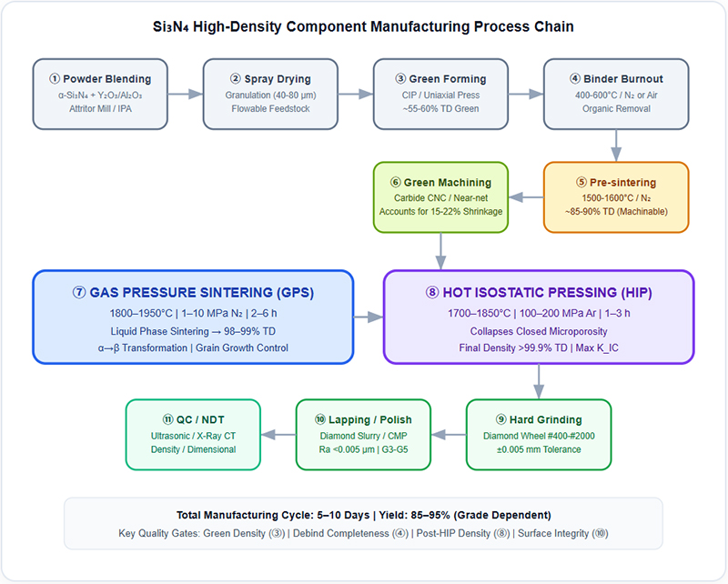
The following diagram maps the complete 11-stage process from raw powder blending through final NDT qualification. Each stage has defined quality gates and process windows critical to achieving >99.9% density.
Diagram 1: High-Density Si₃N₄ Component Manufacturing Process Flow
GPS vs. HIP: Complementary Densification Mechanisms
Achieving >99.9% theoretical density requires two distinct physical mechanisms operating sequentially. Neither GPS nor HIP alone is sufficient for bearing-grade Si₃N₄.
Gas Pressure Sintering (GPS)
Primary Consolidation
T: 1800-1950°C | P: 1-10 MPa N₂
Dwell: 2-6 hours
Mechanism: Liquid phase sintering (solution-reprecipitation through YASAN melt)
Density Achieved: 98-99% TD
Functions: Suppresses Si₃N₄ decomposition (shifts equilibrium via Le Chatelier); enables α→β transformation; closes open porosity network
Limitation: Isolated closed pores (<1 μm) trapped at grain triple junctions remain; these are potential fatigue initiation sites
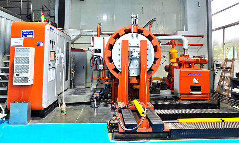
Hot Isostatic Pressing (HIP)
Defect Elimination
T: 1700-1850°C | P: 100-200 MPa Ar
Dwell: 1-3 hours
Mechanism: Hydrostatic plastic flow + diffusional creep collapse of closed pores
Density Achieved: >99.9% TD
Functions: Eliminates residual closed microporosity; heals internal microcracks; increases Weibull modulus from ~12 to >20
Prerequisite: Part must have ONLY closed porosity (no open channels to surface); GPS must precede HIP
Why Not HIP Alone? The Open/Closed Porosity Distinction
HIP applies uniform hydrostatic pressure via gas medium. If the green body contains open porosity (interconnected pore channels reaching the surface), pressurized Ar penetrates the entire pore network, equalizing internal and external pressure-resulting in zero net densification force. GPS first eliminates open porosity through liquid phase flow and grain rearrangement, sealing all pores as isolated closed voids. Only then can HIP's hydrostatic pressure create the differential needed to plastically collapse those voids. This sequential requirement is fundamental to Si₃N₄ processing.
α→β Phase Transformation & Microstructural Toughening Mechanisms
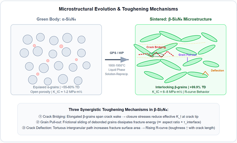
The fracture toughness of Si₃N₄ (6-8 MPa·m½) is not an intrinsic crystal property-it is an engineered emergent property arising from controlled microstructural development during liquid phase sintering. Understanding this transformation is essential to understanding why Si₃N₄ outperforms all other monolithic ceramics in dynamic structural applications.
Diagram 2: α→β Transformation & Crack-Toughening Mechanisms in Sintered Si₃N₄
Solution-Reprecipitation Kinetics
Small α-grains dissolve preferentially (higher surface energy/curvature) into the YASAN melt and reprecipitate onto existing β-nuclei as elongated crystals. This Ostwald ripening is governed by the Gibbs-Thomson effect. Aspect ratios of 5-15:1 are achieved by controlling temperature ramp rate, dwell time, and additive chemistry. Faster heating favors higher nucleation density → finer grains; slower heating favors fewer nuclei → coarser, higher-aspect-ratio grains with greater toughness.
Grain Boundary Phase Engineering
After cooling, a thin (0.5-2 nm) amorphous oxynitride film remains at grain boundaries. This glassy phase controls high-temperature creep and oxidation resistance. Post-sintering annealing at 1400-1600°C devitrifies this film into crystalline silicates (e.g., Y₂Si₂O₇, melilite), raising the glass transition temperature from ~900°C to >1300°C. This is essential for turbine and aerospace components operating above 1000°C.
Precision Diamond Finishing & Surface Integrity Control
Fully sintered Si₃N₄ (HV 1500-1700) exceeds the hardness of all conventional cutting tools. All dimensional finishing requires diamond abrasives, and the process must be carefully controlled to avoid introducing subsurface damage that compromises fatigue performance.
| Process Stage | Tool / Media | Achievable Tolerance | Critical Parameters |
|---|---|---|---|
| Green Machining | WC / HSS CNC | ±0.1 mm | Pre-sintered (~85% TD); fast material removal; account for 15-22% linear shrinkage |
| Rough Grinding | Metal-bond Diamond #120-#220 | ±0.02 mm | Depth ≤20 μm/pass; flood coolant; removes sintering skin and shape errors |
| Fine Grinding | Resin-bond Diamond #400-#2000 | ±0.005 mm | Depth ≤5 μm/pass; induces beneficial compressive residual stress; minimizes subsurface crack depth |
| Lapping | Diamond Slurry + CI Plate | ±0.001 mm | Removes grinding damage layer entirely; achieves G3-G5 sphericity for bearing balls |
| Superfinishing / CMP | Colloidal Silica / Mag. Abrasive | Ra < 0.005 μm | Mirror finish; zero subsurface damage; required for semiconductor and optical grades |
Critical: Subsurface Damage Management
Aggressive diamond grinding introduces a damaged surface layer consisting of median/radial microcracks extending 20–50 μm below the surface. These cracks serve as fatigue initiation sites under cyclic loading, potentially reducing bearing life by an order of magnitude. Mandatory mitigation includes: (1) Progressive grit refinement (never skip more than two grit sizes); (2) Final fine-grind depth ≤3 μm/pass; (3) Minimum lapping stock removal ≥2× measured crack depth (verified by tapered cross-div microscopy); (4) XRD sin²ψ residual stress measurement confirming compressive surface state (target: -200 to -500 MPa).
Critical Applications Enabled by High-Density Si₃N₄
Hybrid Bearing Balls & Rollers
Critical Requirement: >99.9% TD, G3-G5 sphericity, zero subsurface defects (ISO 26602).
Performance Gain: 60% weight reduction → 60% lower centrifugal load; electrical insulation eliminates EDM fluting; 3-10× L₁₀ fatigue life vs. steel. Standard in EV traction motors, CNC spindles, wind generators, and rocket turbopumps.
Semiconductor Fab Equipment
Critical Requirement: Ultra-high purity (>99.99%), plasma erosion resistance, near-zero particle generation.
Performance Gain: Etch focus rings, CVD wafer boats, CMP retainers survive aggressive CF₄/O₂ plasmas and 1200°C furnace cycles without metallic contamination. 5-10× longer service life vs. quartz or Al₂O₃.
Automotive Powertrain Components
Critical Requirement: Thermal shock resistance (ΔT >800°C), retained strength at 1000°C+, wear resistance.
Performance Gain: Turbocharger rotors (40% lighter → reduced lag), glow plugs, valve train followers, fuel injector nozzles. Enables higher EGT and improved thermal efficiency.
Metal Cutting Tool Inserts
Critical Requirement: Hot hardness retention, chemical inertness vs. Fe-based alloys.
Performance Gain: Machines gray cast iron and nickel superalloys at 2–3× carbide speeds. No crater wear with steel (unlike WC-Co). Ideal for high-speed turning, milling, and hard part machining (>45 HRC).
Welding & Thermal Processing Fixtures
Critical Requirement: Electrical insulation, thermal stability, non-wetting to molten metals.
Performance Gain: Weld nozzle tips, brazing fixtures, soldering pallets. Does not adhere to weld spatter; electrically isolates workpieces; survives thousands of thermal cycles without degradation.
Industrial Wear & Corrosion Parts
Critical Requirement: Combined abrasion + corrosion resistance.
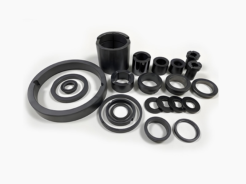
Performance Gain: Mechanical seal faces, blast nozzles, extrusion dies, pump plungers. Outlasts tungsten carbide in acidic/alkaline slurry environments where WC suffers binder leaching and chemical attack.
Final Properties: HIP-Densified Si₃N₄ (Bearing Grade)
| Property | Typical Value (HIP Si₃N₄) | Engineering Significance |
|---|---|---|
| Density | 3.20-3.25 g/cm³ (>99.9% TD) | Eliminates porosity-driven fatigue; enables reliable Weibull statistics |
| Flexural Strength (RT) | 800-1200 MPa | Highest among monolithic structural ceramics |
| Fracture Toughness (KIC) | 6.0-8.0 MPa·m½ | 2–3× Al₂O₃; enables dynamic/shock-loaded applications |
| Vickers Hardness (HV10) | 1500-1700 | Exceptional abrasion and debris denting resistance |
| Young's Modulus | 300-320 GPa | 50% stiffer than steel → smaller Hertzian contact → less spin-slip |
| Thermal Shock Resistance (ΔTc) | >800°C | Survives water quench from red heat; unmatched among engineering ceramics |
| Max Continuous Service Temp | 1200-1400°C | Retains >80% RT strength at 1000°C (steel loses >90%) |
| Volume Resistivity | >10¹⁴ Ω·cm | Perfect dielectric; blocks EDM currents in VFD motors |
| CTE | 3.2 × 10⁻⁶ /K | ¼ of steel → stable preload in hybrid bearings across thermal range |
| Weibull Modulus (m) | 15-30 (HIP grade) | High reliability; narrow strength distribution for design allowables |
Engineering Frequently Asked Questions
Q1: What is the typical linear shrinkage during Si₃N₄ sintering, and how is it managed?
Linear shrinkage during GPS is typically 15-22% (volumetric: 40–50%), depending on green density, additive content, and particle size distribution. Shrinkage is managed by: (1) Precise green density control via CIP pressure calibration; (2) Uniform granule morphology from spray drying; (3) Oversized green machining with shrinkage-compensated CAD models; (4) Statistical process control tracking batch-to-batch shrinkage variation (target: ±0.3%). Anisotropic shrinkage (<1% difference axial vs. radial) occurs in uniaxially pressed parts due to green density gradients; CIP-formed parts exhibit isotropic shrinkage.
Q2: Can Si₃N₄ be joined to metals or other ceramics?
Yes, using specialized techniques. Active metal brazing (Ag-Cu-Ti filler, e.g., Cusil-ABA) reacts with Si₃N₄ to form TiN/Ti₅Si₃ interlayers, achieving joint strengths of 200-400 MPa. Diffusion bonding with Ni or Mo interlayers produces high-temperature-capable joints. The primary challenge is CTE mismatch (Si₃N₄: 3.2 ppm/K vs. steel: 12 ppm/K), which generates residual tensile stresses during cooldown. Mitigation strategies include compliant interlayers (Cu, Kovar), graded composite transitions, and joint geometry optimization to minimize stress concentration.
Q3: How does Si₃N₄ compare to SiC and ZrO₂ for structural applications?
vs. SiC: Si₃N₄ offers 2× fracture toughness (6-8 vs. 3-4 MPa·m½) and superior thermal shock resistance, but lower thermal conductivity (30 vs. 120 W/m·K) and oxidation limit (~1400°C vs. 1600°C). Choose Si₃N₄ for dynamic/shock-loaded parts; SiC for static high-temp heat exchangers. vs. ZrO₂ (Y-TZP): Si₃N₄ retains strength to 1200°C+ (ZrO₂ degrades above 800°C due to tetragonal→monoclinic transformation and grain growth). ZrO₂ has higher RT toughness (8-12 MPa·m½) but is unsuitable for sustained high-temperature service. Si₃N₄ offers the best overall balance for high-temperature dynamic structural applications.
Q4: What NDT methods qualify bearing-grade Si₃N₄ components?
Bearing-grade Si₃N₄ undergoes multi-modal NDT per ISO 26602 and customer specifications: (1) Ultrasonic immersion testing (50-100 MHz focused transducers) detects subsurface pores, inclusions, and cracks >10 μm equivalent diameter; (2) X-ray computed tomography provides 3D volumetric defect mapping with voxel resolution ≤5 μm; (3) Fluorescent penetrant inspection (FPI) reveals surface-breaking flaws; (4) Archimedes density verification confirms >99.9% TD (tolerance: ±0.002 g/cm³); (5) Optical surface inspection under UV/visible light for scratches, pits, and discoloration. Every bearing ball is individually inspected; statistical sampling is insufficient for safety-critical applications.