





The Silicon Nitride Sintering Challenge
Silicon nitride (Si₃N₄) is one of the most technically challenging advanced ceramics to manufacture. Unlike oxide ceramics (Al₂O₃, ZrO₂) that sinter readily via solid-state diffusion, Si₃N₄ is a covalently bonded compound with extremely low self-diffusion coefficients. It cannot achieve full density through conventional pressureless sintering alone. Furthermore, Si₃N₄ is thermodynamically unstable at the temperatures required for densification-it begins to decompose into elemental silicon and nitrogen gas above 1800°C at atmospheric pressure.
Overcoming these barriers requires a sophisticated combination of liquid phase sintering (using oxide additives to form a transient glassy phase), elevated nitrogen overpressure (to suppress decomposition), and often hot isostatic pressing (to eliminate residual porosity). The result is a material with >99.9% theoretical density, exceptional fracture toughness, and the reliability demanded by aerospace, automotive, and semiconductor industries.
Raw Powder Characteristics & Sintering Additives
The quality of the final Si₃N₄ component is fundamentally determined by the starting powder characteristics and the carefully engineered additive system.
α-Si₃N₄ Powder Requirements
Phase Purity: >95% α-phase (transforms to β during sintering for toughening)
Particle Size: D50 = 0.2-0.5 μm (submicron for enhanced sinterability)
Oxygen Content: Controlled 1.0-2.0 wt% (forms SiO₂ layer aiding liquid phase)
Metallic Impurities: Fe, Al, Ca < 50 ppm each (prevents degradation)
BET Surface Area: 10–20 m²/g (optimal reactivity balance)
Sintering Additive Systems
Pure Si₃N₄ cannot sinter. Oxide additives react with surface SiO₂ to form a Y-Si-Al-O-N (YASAN) liquid phase at ~1700°C that enables solution-reprecipitation densification:
Y₂O₃ + Al₂O₃: Most common system; optimal viscosity & wetting
MgO / MgSiN₂: Promotes faster densification at lower temps
Rare Earth Oxides (Lu₂O₃, Yb₂O₃): Higher refractoriness for high-temp applications
Total Additive: Typically 5-12 wt% (balance of density vs. high-temp creep)
Complete Manufacturing Process Flow
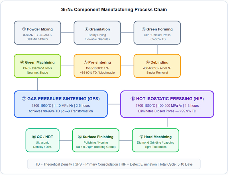
The following diagram illustrates the end-to-end manufacturing sequence from raw powder to finished high-density Si₃N₄ components:
Diagram 1: High-Density Si₃N₄ Component Manufacturing Process Flow
GPS vs. HIP: Two-Stage Densification Strategy
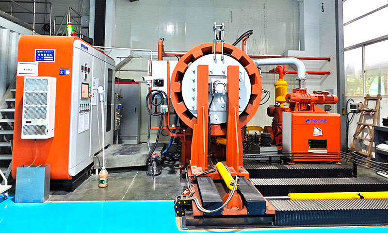
Gas Pressure Sintering (GPS)
Primary Consolidation Step
Temperature: 1800-1950°C
N₂ Pressure: 1-10 MPa
Dwell Time: 2-6 hours
Achieved Density: 98-99% TD
Key Function: Suppresses Si₃N₄ decomposition, enables liquid phase formation, drives α→β transformation
Limitation: Cannot eliminate isolated closed pores trapped within grains
Hot Isostatic Pressing (HIP)
Post-Sintering Densification
Temperature: 1700-1850°C
Ar Pressure: 100-200 MPa
Dwell Time: 1-3 hours
Achieved Density: >99.9% TD
Key Function: Hydrostatic pressure collapses closed microporosity, heals internal defects
Result: Maximizes Weibull modulus, fatigue life, and fracture toughness
Extended Knowledge: Why Not Just Use HIP Alone?
HIP requires the part to already have closed porosity (no open pore channels connected to the surface). If a green body with open pores is HIP'd, the pressurized gas penetrates the pore network and no densification occurs. GPS first closes the open pores via liquid phase sintering, creating isolated closed voids that HIP can then collapse. This two-stage approach is essential for achieving both full density and complex geometries.
α-to-β Phase Transformation & Microstructural Toughening
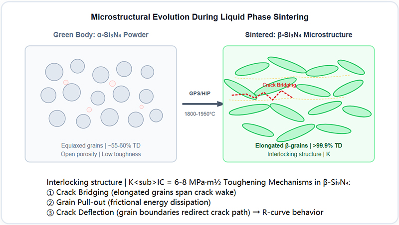
The exceptional fracture toughness of Si₃N₄ is not inherent to the crystal structure-it is engineered through controlled microstructural development during sintering. The transformation from equiaxed α-grains to elongated β-grains creates an interlocking microstructure that resists crack propagation.
SVG Diagram 2: α→β Phase Transformation & Crack Bridging Mechanism
Solution-Reprecipitation Mechanism
During liquid phase sintering, small α-Si₃N₄ grains dissolve into the Y-Si-Al-O-N melt and reprecipitate as elongated β-Si₃N₄ crystals on existing β-nuclei. This Ostwald ripening process is driven by the lower surface energy of β-grains and produces aspect ratios of 5-10:1, which are critical for toughening.
Grain Boundary Engineering
The thin (~1-2 nm) amorphous grain boundary film left after cooling controls high-temperature creep resistance. Post-sintering heat treatments can devitrify this glassy phase into crystalline silicates, dramatically improving creep resistance at >1200°C for turbine and aerospace applications.
Precision Machining & Surface Finishing
Fully sintered Si₃N₄ has a hardness of HV 1500-1700, making conventional machining impossible. All dimensional finishing must be performed with diamond abrasives, and the strategy depends heavily on whether machining is done before or after final densification.
| Stage | Method | Tolerance | Notes |
|---|---|---|---|
| Green Machining | Carbide / HSS CNC | ±0.1 mm | Pre-sintered body (~85% TD); fast, low cost; accounts for 15-20% shrinkage |
| Hard Grinding | Diamond Wheel (Resin/Metal Bond) | ±0.005 mm | Fully sintered; generates compressive surface stresses; coolant mandatory |
| Lapping / Honing | Diamond Slurry + Cast Iron Plate | ±0.001 mm | For bearing balls; achieves G3-G5 sphericity; removes grinding damage layer |
| Superfinishing / Polishing | CMP / Magnetic Abrasive | Ra < 0.005 μm | Mirror finish for optical/semiconductor grades; eliminates subsurface microcracks |
Critical: Avoiding Grinding-Induced Damage
Aggressive grinding of sintered Si₃N₄ can introduce subsurface microcracks up to 20-50 μm deep that act as fatigue initiation sites. Proper process control includes: light depth-of-cut (<5 μm/pass), adequate coolant flow, fine-grit wheels (#400+), and mandatory post-grinding lapping/polishing to remove the damaged layer. For bearing-grade components, X-ray diffraction residual stress measurement is used to verify surface integrity.
Critical Applications of High-Density Si₃N₄ Components
Hybrid Bearing Balls & Rollers
Requirement: >99.9% density, G3-G5 sphericity, zero subsurface defects.
Benefit: 60% lighter than steel, electrically insulating, 3-10× fatigue life. Used in EV motors, machine tool spindles, wind turbines, and aerospace turbopumps.
Semiconductor Equipment Parts
Requirement: Ultra-high purity (>99.99%), plasma erosion resistance, low particle generation.
Benefit: Etch focus rings, CVD wafer boats, CMP retainers. Survives aggressive fluorocarbon plasmas and 1200°C furnace cycles without contaminating wafers.
Automotive Engine Components
Requirement: Thermal shock resistance, high-temperature strength, wear resistance.
Benefit: Turbocharger rotors (reduced lag), glow plugs, valve train followers, fuel injection nozzles. Enables higher combustion temperatures and improved efficiency.
Metal Cutting Tools & Inserts
Requirement: High hot hardness, chemical inertness vs. iron-based alloys.
Benefit: Machines cast iron and superalloys at 2-3× the speed of carbide. No crater wear with steel due to chemical stability. Ideal for high-speed turning and milling.
Welding & Thermal Fixtures
Requirement: Non-conductive, thermally insulating, resistant to molten metal splash.
Benefit: Welding nozzle tips, locating pins, brazing fixtures. Does not stick to weld spatter, electrically isolates workpieces, survives repeated thermal cycling.
Industrial Wear Parts
Requirement: Extreme abrasion resistance, corrosion immunity.
Benefit: Pump seals, blast nozzles, thread guides, extrusion dies. Outlasts tungsten carbide in corrosive-abrasive environments where WC suffers chemical attack.
Final Properties of High-Density HIP'd Si₃N₄
| Property | Value (HIP Si₃N₄) | Significance |
|---|---|---|
| Density | 3.20-3.25 g/cm³ (>99.9% TD) | Near-theoretical; eliminates porosity-related failures |
| Flexural Strength | 800-1200 MPa | Highest among structural ceramics |
| Fracture Toughness (KIC) | 6.0-8.0 MPa·m½ | 2-3× higher than Al₂O₃; enables dynamic loading |
| Hardness (HV) | 1500-1700 | Exceptional wear and abrasion resistance |
| Thermal Shock (ΔT) | >800°C | Survives quenching from red-hot to water |
| Max Service Temperature | 1200-1400°C (load-dependent) | Retains >80% RT strength at 1000°C |
| Electrical Resistivity | >10¹⁴ Ω·cm | Perfect insulator for EDM prevention |
| Weibull Modulus (m) | 15-30 (HIP grade) | High reliability; predictable failure statistics |
Engineering Frequently Asked Questions (FAQ)
Q1: What is the typical shrinkage during Si₃N₄ sintering?
Linear shrinkage during GPS sintering is typically 15-22%, depending on green density and additive content. Volumetric shrinkage is approximately 40-50%. This must be precisely accounted for in green machining allowances. Shrinkage is isotropic for CIP-formed parts but may be slightly anisotropic for uniaxially pressed components due to green density gradients.
Q2: Can Si₃N₄ be joined or brazed to metals?
Yes, but it requires specialized techniques. Active metal brazing (using Ti-containing filler alloys like Ag-Cu-Ti) creates strong joints by reacting with the Si₃N₄ surface to form TiN/Ti₅Si₃ interlayers. Direct bonding and diffusion bonding are also possible. The key challenge is managing CTE mismatch (Si₃N₄: 3.2 ppm/K vs. steel: 12 ppm/K), which requires compliant interlayers or graded joints to prevent cracking during cooldown.
Q3: How does Si₃N₄ compare to SiC and ZrO₂ for structural applications?
vs. SiC: Si₃N₄ has superior fracture toughness (6-8 vs. 3-4 MPa·m½) and thermal shock resistance, but lower thermal conductivity and oxidation resistance above 1400°C. vs. ZrO₂: Si₃N₄ retains strength at much higher temperatures (ZrO₂ degrades above 800°C due to phase instability), but ZrO₂ has higher room-temperature toughness. Si₃N₄ offers the best overall balance for high-temperature dynamic applications.
Q4: What NDT methods are used to qualify high-density Si₃N₄ components?
Critical components undergo multiple NDT inspections: Ultrasonic testing (pulse-echo, 50-100 MHz) detects subsurface pores and inclusions >10 μm. X-ray CT scanning provides 3D volumetric defect mapping. Dye penetrant inspection reveals surface-breaking cracks. Fluorescent penetrant inspection (FPI) is used for aerospace bearing balls. Density verification via Archimedes method confirms >99.9% TD. Every bearing-grade ball is individually inspected per ISO 26602.